Beware of cowboy fibre installers
Below is a fibre report carried out by one of King Comms NI ltd engineers earlier this week. The worrying thing about this installation is the amount of time it went unnoticed, which means the fibres were not working as they should but were as good as the customer expected, as in they didn’t know any better. Please be sure that you are satisfied with any work that has been undertaken and if you have any concerns, you should always seek third party professional advice from qualified data network installation engineers.
Our observations
Whilst decommissioning the fibre optic patch panel within the accommodation block XXXXXXXXX, the following observations were made.
- The fibre type is OM1 62.5/125 micron fibre, this is the oldest standard of multimode fibre and is obsolete.
- Burnt and incorrectly installed fibre splice protectors
- Macro bends within the fibre splice tray
- Bare fibres which can be damaged easily
- Failure to pass standard ISO OM1 fibre test results.
- No signal or too poor a signal
- Untidy and unprofessional installation
Other observations
- The education block fibre is short within the admin block end. In order for this to be re-spliced, a junction box and extender will have to be installed.
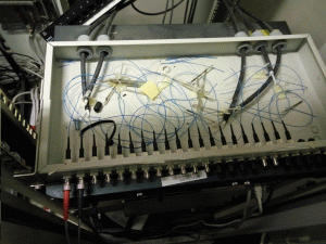
An overview of the fibre splice tray showing untidy install and general bad practice (fig a)
Fig a
More information
Fibre type
The OM1 standard of fibre can transmit Ethernet at 1GbE up to 300metres but can only carry 10GbE around 40m. Due to installation distances at XXXXXXXXX, to upgrade to 10GbE, OM4 would be recommended.
Burnt Splice protectors
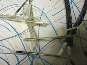
Splice protectors shrink in a curing oven to form a stable protection over the splice. The burns on the fibres at XXXXXXXXX are probably due to too hot a curing oven or too long in the oven. The red circle clearly shows a burnt splice protector with other examples of this evident in the picture.
Fig 1
Macro bends
Macro bends are tight bends which can cause light loss and effect cable performance. Fig 2 shows an example of a macro bend in the splice tray within the admin block at XXXXXXXXX (detailed by red circle)
Fig 2
Bare Fibres
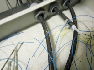
12mm of sheath should be visible on both fibres after cleaving, leaving 24mm of bare fibre after the two ends have been spliced together. This allows for the splice protector to neatly clamp down over the sheath of both fibres, giving a strong join within the single fibre strand. As you can see from fig 3 (below), the fibre has been stripped excessively leaving bare fibres visible at either end of the splice protector. These bare fibres are brittle and can easily break. Please see fig1, highlighted by a purple circle.
Test results
Our attached report (2015-000142), made using a level 3 DTX1800 state of the art cable analyser, clearly shows that the fibres are not performing to ISO11801 as they should be. Where test reports are missing (Block B fibres 1 – 4, Education fibres 1 – 2, & Block A fibres 3 – 4), too little signal was available to generate a test.
Our actions so far
In agreement with XXXXXXXXXX, we removed the existing fibre splice tray in the admin block XXXXXXXXX. This will need to be reinstated.
Our recommendations
As a minimum, a review should be made of all other fibre splice panels on XXXXXXXXX to ascertain whether remedial works will be required within the existing fibre termination points of all buildings. Upon correct reinstallation of the fibre panel in the admin block, any points still failing the standard fibre test, shall have to be repaired at the termination point with in the appropriate building.
Due to increasingly bandwidth hungry applications, our recommendation is to replace all the OM1 cable with OM4. This will ensure that XXXXXXXXX will be able to run future applications on their backbone network infrastructure.


